


 1131
1131
INSTALLATION INSTRUCTIONS
STEP 1 – SHAFT PREPARATION
Wipe the shaft clean and remove any burrs that could cause the bearing race to deform when the setscrews are tightened down. Proper shaft diameter is CRITICAL. Check the shaft diameter against the specifications shown in Table 3. Undersized shafting is one of the leading causes of bearing failure. If the shaft is not within the tolerance shown in Table 3, its use may lead to premature bearing failure.
STEP 2 – BASE PREPARATION
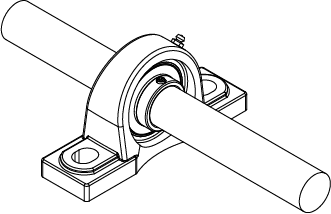
Slide the bearing on the shaft to the desired position. DO NOT use anti-seize style lubricant on the shaft or bearing. Leave the setscrews loose. Secure housing in place with bolts.
STEP 3 – MOUNTING OF HOUSING
Turner recommends applying an anaerobic locking compound to cap screws before tightening. A general-purpose, medium-strength option like Loctite 243 threadlocker is acceptable.
3.a Setscrew Style Bearings (UC, UCX, SB, CSB, SER)
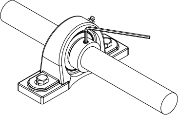
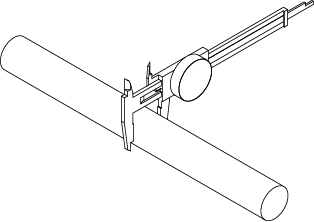
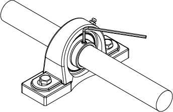
Begin tightening both setscrews down alternately with the proper torque shown in Table 1 until both setscrews are locked to the shaft.
3.b Eccentric Style Bearings (HC, SA, CSA)
Place the eccentric collar on the bearing’s inner ring and turn in the direction of rotation until the eccentric grooves engage, locking the collar to the bearing. Use a drift or punch in the hole of the collar and drive it with a hammer in the direction of the shaft’s rotation. This will help to ensure the lock on the shaft. Tighten the collar’s setscrew using the torque recommended in Table 1.
3.c Tru-Loc Style Bearings (UE AND UER)
Place the clamping collar over the inner ring of the bearing. Tighten clamping bolt to the torque value shown in Table 2.
| Set Screw Size | Bearing Number | Torque | |||||||
|---|---|---|---|---|---|---|---|---|---|
| Metric | Inch | in-lbs | N-m | ||||||
| M6 x 0.75 | 1/4-28 UNF | UC201-206 | UCX05 | HC201-205 | SA/CSA201-206 | SB/CSB201-206 | SER201-206 | 35 | 4.0 |
| M8 x 1.0 | 5/16-24 UNF | UC207-209 | UCX06-X08 | HC206-210 | SA/CSA207-211 | SB/CSB207-211 | SER207-209 | 78 | 8.8 |
| M10 x 1.25 | 3/8-24 UNF | UC210-213 | UCX09-X12 | HC211-215 | SA/CSA212 | SB/CSB212 | SER210-212 | 156 | 17.6 |
| M12 x 1.5 | 7/16-20 UNF | UC214-215 | UCX12-X17 | — | — | — | — | 243 | 27.5 |
| M16 x 1.5 | 5/8-18 UNF | — | UCX20 | — | — | — | — | 521 | 58.9 |
| Unit Size | Torque | ||
|---|---|---|---|
| in-lbs | N-m | ||
| UE204-206 | UER204-206 | 70 | 7.9 |
| UE207-209 | UER207-209 | 90 | 10.2 |
| UE210-211 | UER210-211 | 180 | 20.3 |
| UE212 | UER212 | 400 | 45.2 |
| Shaft Diameter | Shaft Tolerance | ||||
|---|---|---|---|---|---|
| Over | Including | ||||
| mm | in | mm | in | h7 | |
| 10 | 0.394 | 18 | 0.709 | 0 | -18 |
| 0 | (-7) | ||||
| 18 | 0.709 | 30 | 1.181 | 0 | -21 |
| 0 | (-8) | ||||
| 30 | 1.181 | 50 | 1.969 | 0 | -25 |
| 0 | (-10) | ||||
| 50 | 1.969 | 80 | 3.150 | 0 | -30 |
| 0 | (-12) | ||||
| 80 | 3.150 | 120 | 4.724 | 0 | -35 |
| 0 | (-14) | ||||
| 120 | 4.724 | 140 | 5.512 | 0 | -40 |
| 0 | (-16) | ||||
If all the steps above have been followed, the bearing mounting is complete.
REMOVAL INSTRUCTIONS
Setscrew Style
Loosen the setscrews from the shaft. Then unbolt the housing from the support surface. Often, the bearing will adhere to the shaft. In this situation, use a bearing puller or hammer and drift to remove the bearing. Check for proper shaft fits (shown in Table 3) and damage prior to the next installation.
Eccentric Collar Style
Loosen the setscrew in the collar. Use a drift or punch in the hole of the collar and drive it with a hammer in the opposite direction of the shaft’s rotation. Once the collar is loose, slide it away from the bearing. Remove any burrs from the setscrew before remounting the bearing. Unbolt the housing from the support surface. Often the bearing will adhere to the shaft. In this situation use a bearing puller or hammer and drift to remove the bearing. Check for proper shaft fits (shown in Table 3) and damage prior to the next installation.
Tru-Loc Style
Loosen the clamping collar bolt and remove it from the inner ring of the bearing. Then unbolt the housing from the support surface. Often the bearing will adhere to the shaft. In this situation, use a bearing puller or hammer and drift to remove the bearing. Check for proper shaft fits (shown in Table 3) and damage prior to the next installation.
Associated Part Numbers
UCP, UCPX, HCP, UEP, HCAK, UCTB, HCTB, UETB, UCF, UCFX, UEF, HCFS, UCFT, UCFL, UEFT, HCFJT, SALF, SBLF, UCFB, UCFBS, UEFB, UEFBS, SARFB, SBRFB, UCFC, UCFCS, UCFCSX, UEFC, UEFCS, UCST, HCST, UEST, UCHA, UEHA


