


 218
218
INSTALLATION INSTRUCTIONS
STEP 1 – SHAFT PREPARATION
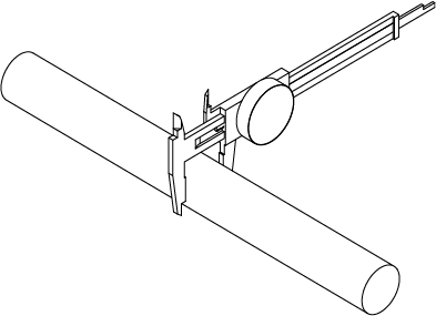
Wipe the shaft clean and remove any burrs that could restrict the installation or deform the bearing ring when the setscrews are tightened down. Proper shaft diameter is CRITICAL. Check the shaft diameter against the specifications shown in Table 2. Undersized shafting is one of the leading causes of reduced bearing life. If the shaft is not within the tolerance shown in Table 2, use may result in reduced bearing life.
STEP 2 – MOUNTING
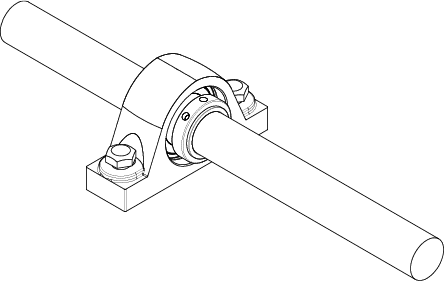
Slide the bearing on the shaft to the desired position. DO NOT use anti-seize style lubricant on the shaft or bearing. Leave any setscrews loose on the shaft.
STEP 3 – BASE PREPARATION
Make sure that the base of the mounted bearing and support surface are clean and flat. Any unevenness in the surface can interfere with proper bearing alignment and lead to premature failure. Securely fasten the mounted bearing to the support surface using the machinery manufacturer’s recommendations.
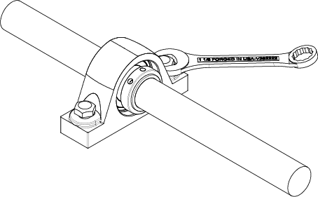
CONCENTRIC COLLAR TIGHTENING
NOTE: Turner recommends applying an anaerobic locking compound to cap screws before tightening. A general-purpose, medium-strength option like Loctite 243 threadlocker is acceptable.
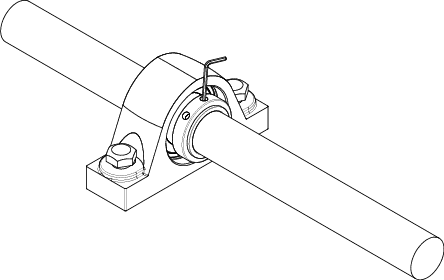
Begin tightening both setscrews down alternately until both setscrews are locked to the shaft at the proper torque shown in Table 1.
If all the steps above have been followed, the bearing mounting is complete.
| Bearing Shaft Diameter (in.) | Setscrew | |
|---|---|---|
| Thread (TPI) | Torque (in-lbs) | |
| 1 15/16 - 2 | 3/8”-24 | 325 |
| 2 3/16 - 2 1/4 | 3/8”-24 | 325 |
| 2 7/16 - 2 1/2 | 1/2”-20 | 680 |
| 2 11/16 - 3 | 1/2”-20 | 680 |
| 3 7/16 | 1/2”-20 | 680 |
| 3 15/16 | 5/8”-18 | 1330 |
| Shaft Diameter (in.) | Shaft Tolerance (in.) |
|---|---|
| 1 - 2 | +0.000 / -0.001 |
| 2 1/16 - 4 | +0.000 / -0.0015 |
REMOVAL INSTRUCTIONS
Loosen the setscrews from the shaft. Then unbolt the housing from the support surface. Often, the bearing will adhere to the shaft. In this situation, use a bearing puller or hammer and drift to remove the bearing.
For spherical flange cartridge bearings (SFC series), there are threaded removal holes to aid in backing the housing out of the cartridge hole.
These removal holes are designated by the dimension “S” and the appropriate thread size is listed for each housing on the SFC series (below). For convenience, pry-slots are located 90 degrees from the threaded removal holes.
|
Bearing
Number |
d | Dimensions (in.) | Bolt Hole T (in.) |
Removal Hole S (in.) | Dynamic Load Capacity Cr (lbs)(KN) |
Static Load Capacity Cor (lbs)(KN) |
||||||||
|---|---|---|---|---|---|---|---|---|---|---|---|---|---|---|
| P | A | Z* | J | BL | F | K | G | Qty | Size | |||||
| SFC 1 15/16 T | 1-15/16 | 5.375 | 6.375 | 3.156 | 1.594 | 2.875 | 4.500 | 2.875 | 0.563 | 0.531 | 2 | 7/16-14 UNC | 20,460 91.0 |
25,630 114.0 |
| SFC 2 T | 2 | |||||||||||||
| SFC 2 3/16 T | 2-3/16 | 6.000 | 7.125 | 3.313 | 1.656 | 3.125 | 5.000 | 3.250 | 0.563 | 0.594 | 2 | 1/2-13 UNC | 23,600 105.0 |
28,325 126.0 |
| SFC 2 1/4 T | 2-1/4 | |||||||||||||
| SFC 2 7/16 T | 2-7/16 | 6.500 | 7.625 | 3.500 | 1.688 | 3.375 | 5.500 | 4.000 | 0.625 | 0.594 | 2 | 1/2-13 UNC | 37,630 167.4 |
46,960 208.9 |
| SFC 2 1/2 T | 2-1/2 | |||||||||||||
| SFC 2 11/16 T | 2-11/16 | 7.500 | 8.750 | 3.906 | 2.031 | 3.625 | 6.375 | 4.500 | 0.688 | 0.750 | 2 | 5/8-11 UNC | 41,590 185.0 |
53,050 236.0 |
| SFC 2 3/4 T | 2-3/4 | |||||||||||||
| SFC 2 15/16 T | 2-15/16 | |||||||||||||
| SFC 3 T | 3 | |||||||||||||
| SFC 3 7/16 T | 3-7/16 | 8.625 | 10.250 | 4.219 | 1.938 | 4.031 | 7.375 | 5.125 | 0.875 | 0.875 | 2 | 3/4-10 UNC | 63,280 281.5 |
84,100 374.1 |
| SFC 3 15/16 T | 3-15/16 | 9.375 | 10.875 | 4.813 | 2.406 | 4.594 | 8.125 | 6.000 | 0.875 | 0.875 | 2 | 3/4-10 UNC | 84,410 375.5 |
112,580 500.8 |
*Dimensions listed are for non-expansion units; for expansion type, adjust +/- 0.050".
Associated Part Numbers
SPB2, SPB4, SFC, SFB4


